
Quick answer: measure first with Tools → Statistics, then open Process → DC Offset and use automatic detection or enter the measured correction. Analyze representative programme audio instead of relying on the first five seconds when the file begins with a long mute or fade-in. After correction, run Statistics again and check both average value and peaks.
DC offset is a constant positive or negative component that shifts the waveform’s baseline away from zero. It can waste headroom, create clicks at edits, and produce unexpected results in later processing. A waveform that merely has larger positive than negative peaks isn’t automatically offset, though, so visual diagnosis alone won’t settle it.
DC Offset vs Normal Asymmetry
The diagrams below illustrate the diagnosis and workflow; they are not captured measurements from your file or exact copies of the application windows. A slow oscillation can average near zero over complete cycles and still give a non-zero mean in a shorter selection.
| Observation | Likely cause | Correct test |
|---|---|---|
| Silence sits consistently above or below zero | DC offset | Average value over a representative range |
| Positive peaks are larger, but baseline centers | Natural waveform asymmetry | Longer average near zero |
| Baseline slowly rises and falls | Rumble or subsonic movement | Spectrum/listening and time-varying view |
| 50/60 Hz tone and harmonics | Mains hum | Spectral analysis, not DC correction |
| Click only at one edit | Sample discontinuity | Inspect the edit boundary |
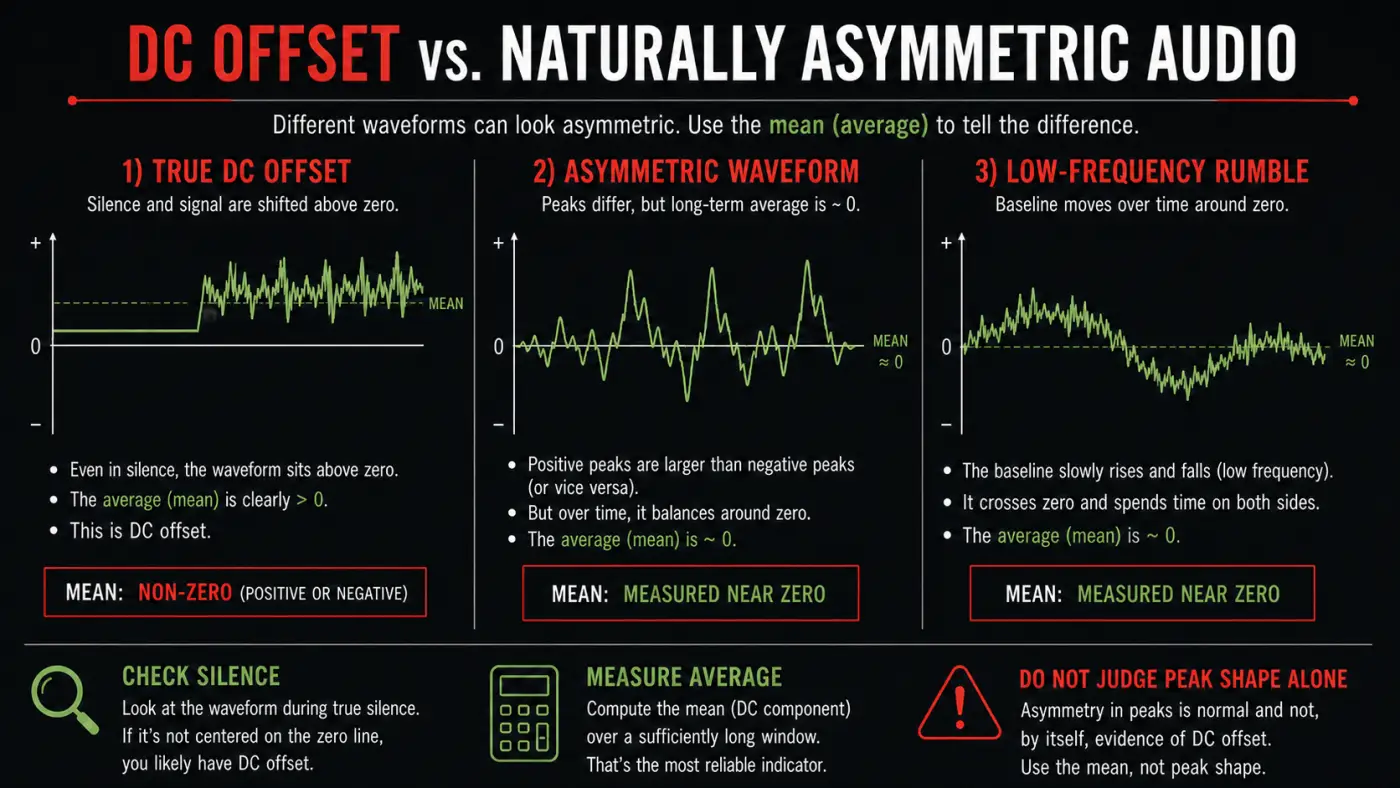
A signal can have unequal positive and negative peaks while its average remains zero. iZotope’s explanation of offset versus waveform asymmetry makes this distinction; the signal principle is not specific to Ozone. Correcting that shape as though it were a constant offset can change the file without solving a problem. A persistent non-zero average across representative captured audio is the stronger test. Captured room tone can reveal a shifted baseline, but inserted digital silence will sit at zero even when the adjoining recording is offset.
Why DC Offset Matters
A positive offset moves every sample upward. That reduces positive headroom while increasing unused negative headroom. Normalization, limiting, distortion, and other nonlinear processing can react differently when the waveform is not centered. Cutting or joining offset material at zero-valued boundaries can also create a step that clicks.
The current Sound Forge 2026 DC Offset documentation warns that glitches and unexpected effects results can occur in offset files. Capture hardware is one possible source, but nonlinear processing can also produce a new mean. A file conversion alone is not enough evidence to diagnose the cause.
Measure the Offset in Statistics
- Open a lossless copy of the source.
- Select a representative range or the complete file.
- Choose Tools → Statistics.
- Record the Average value (DC offset) for each channel.
- Also record positive and negative peaks for comparison.
- Repeat on another representative range if the reading changes materially.
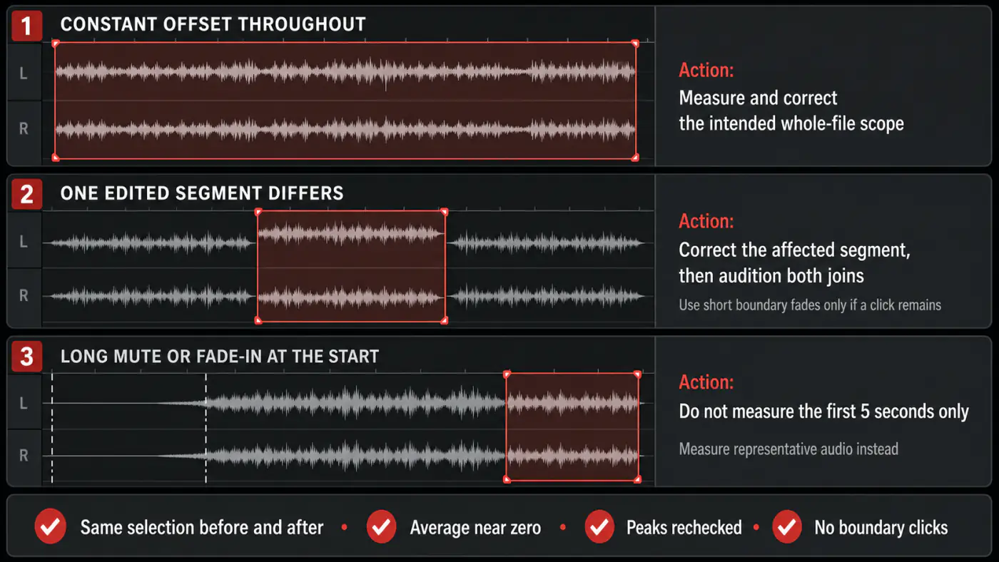
Use enough real audio to avoid a misleading estimate. A file that starts with digital silence will report near zero in that segment even if the later capture is offset. A long fade-in may underrepresent the stable offset. Conversely, a very short asymmetric note can have a non-zero local mean even when the full recording has no constant DC problem.
Boris FX defines Statistics → Average value as the sum of the selected sample values divided by the number of samples; a non-zero result can indicate DC offset. Our Sound Forge Statistics guide covers the rest of the readout. Measure left and right separately because one input channel can be offset more than the other.
Remove DC Offset Automatically
- Select the complete recording with a consistent offset, including all intended channels. For an edited compilation, work on each source section separately.
- Open Process → DC Offset.
- Choose Automatically detect and remove.
- Leave first-five-seconds-only disabled when the beginning is not representative.
- Click OK to process the working copy.
- Reopen Tools → Statistics on the same range and channels; compare the mean and both peak polarities, then listen across the edited boundaries.
Sound Forge offers Compute DC offset from first 5 seconds only to speed analysis. The current help explicitly warns that five seconds may be insufficient when a long fade-in or mute occurs at the beginning. Treat the option as an optimization for uniform material, not a default accuracy setting.
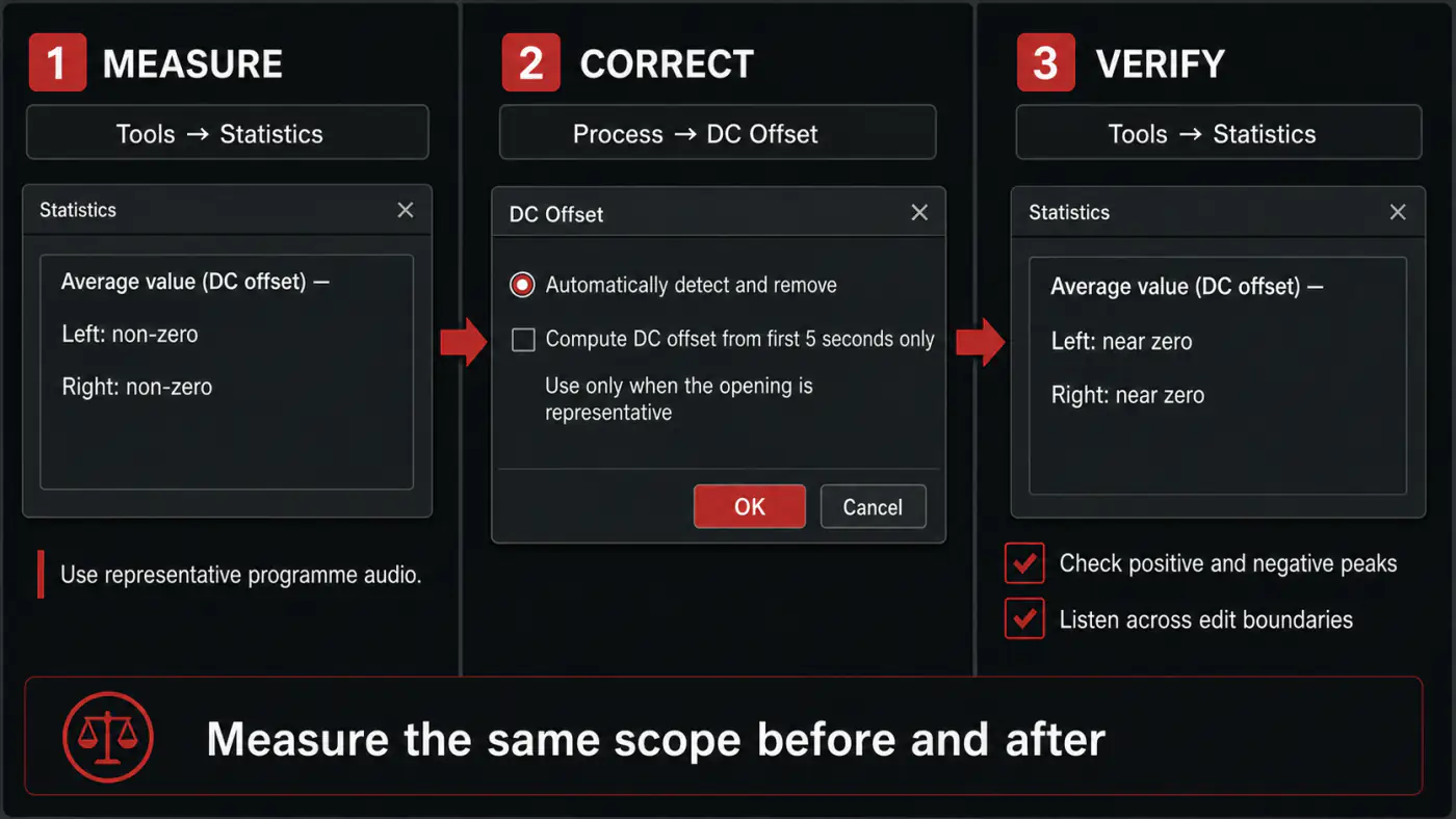
Check the selection before committing. The processing-dialog controls let you inspect Start, End and Channels under More; right-clicking the dialog also provides Select All. If the result differs from the expected constant shift, check for unintended wet/dry gain or processing fades rather than repeatedly applying correction.
Enter a Manual Correction
The documented manual path is to record Average value readings in Statistics, open Process → DC Offset, choose Adjust DC offset by, and enter the correction. Use this when a controlled workflow needs an explicit value or when comparing automatic analysis across selections.
Use a signed linear readout in Statistics, such as Percent or Sample Value, and check that the manual adjustment field uses the same units. A negative dB reading describes magnitude below full scale; it is not negative DC polarity and must not be pasted as an opposite-sign correction.
The current textual DC Offset help does not specify the adjustment field’s units, so confirm them in the installed dialog or use automatic detection instead. For matching linear units, subtract a positive mean and add the magnitude of a negative mean; verify the same channel and analysis range afterward.
Correct Before Gain-Dependent Processing
Correct a meaningful constant offset early, after the capture is safely copied and before normalization, compression, limiting, or nonlinear effects. This removes the constant bias; it does not guarantee equal positive and negative peaks. Natural waveform asymmetry can remain. If an earlier restoration step introduces a new offset, measure again rather than assuming one correction is permanent.
Check for new clipping: subtracting a positive mean also pushes the most-negative sample farther down. As a numerical example, a minimum of −0.98 and a mean of +0.03 become −1.01 after subtraction, outside the nominal ±1 full-scale range. If the correction would exceed the file’s limits, undo it, lower the working-copy level, remeasure the mean and try again. Do not assume that centering always creates more usable peak headroom.
Don’t normalize merely because offset removal changed peak values. First decide whether the delivery needs a peak or loudness adjustment, then follow the normalization workflow from the corrected master.
Why the Result May Not Read Exactly Zero
Subtracting the exact mean from the same analysis range gives zero mean in exact arithmetic; stored-sample rounding can leave a small residual. Measuring a different selection is a different test: a short asymmetric note, fade or low-frequency segment can still have a local mean. A whole-file correction does not force every smaller selection to zero.
Judge improvement across representative ranges. If the full file is centered but one short note reports a local average, using that note’s mean to shift the whole file can introduce a new bias. Repeating exact whole-file mean subtraction on an unchanged file should add no meaningful correction. If the measured offset reappears after filtering, compression, limiting, or asymmetric clipping, inspect that process and its output rather than blindly running removal after every step.
Before treating a new non-zero reading as a fault, compare its magnitude with the earlier reading on exactly the same selection. A tiny displayed residual without a headroom, edit or audible consequence does not justify another processing pass.
DC Offset Is Not Hum or Rumble
DC is 0 Hz: a constant component. Mains hum is usually 50 or 60 Hz plus harmonics, while rumble varies over time. The traditional Sound Forge Process → DC Offset operation changes samples by a constant amount, as described in its DC Offset glossary entry. That is not a hum notch, a rumble filter or a repair for the underlying electrical fault. Use the hiss and hum diagnosis when the problem is audible noise rather than a constant baseline shift.
coreFX Utility is different. Its Remove DC control uses a steep 5 Hz high-pass filter, according to the current help. Filtering can address near-DC drift as well as a constant component, but it can also change the signal. Do not treat Utility and Process → DC Offset as interchangeable settings. For a moving baseline, inspect several time ranges and compare the processed bass and edit boundaries before keeping the result.
Partial Selections and Edit Boundaries
Correcting only part of a file can create different baselines on either side of the selection. Even if each section is valid alone, the join may click. For a constant capture-chain offset, process the coherent recording as a whole. For material assembled from different sources, measure and correct each source before joining, then inspect boundaries.
Inserted digital silence needs special care: subtracting the recording’s offset from zero-valued samples creates a new offset there. The limitations of constant-offset removal also apply to an edited file containing both biased and unbiased sections. Preserve or restore the zero-valued gaps separately, and check both joins.
For an offset repair, use short fades or crossfades after correcting the relevant source sections. The Sound Forge crossfade guide covers boundary continuity; a crossfade should not be used to hide an uncorrected whole-file offset.
Three Diagnostic Scenarios
One Continuous Analogue Capture
A cassette or preamp capture shows a similar positive average across beginning, middle, and end, and its silent lead-in sits above zero. That pattern supports one coherent whole-file correction. Measure the complete programme or several long selections, correct before restoration EQ and limiting, then verify the same ranges, both peak polarities and the joins.
Edited File from Multiple Recorders
The first interview segment measures positive, the second is near zero, and the third is negative. One global average can look acceptable while each section remains offset. Identify source boundaries, correct each coherent recording separately, and crossfade only after their baselines are stable. Keep handles so boundary repairs remain reversible.
Master That Changes After Limiting
The premaster measures near zero, but the limited render reports a persistent mean and shows unequal positive and negative clipping. Compare the input and output of the limiter or nonlinear stage to locate where the mean changed. Check the drive level, saturation and clipping behavior. Removing DC afterward may center the result, but it does not undo distortion that occurred because one side hit the ceiling first. If samples have already been flattened, follow the separate clipped and distorted audio diagnosis.
Prevent the Offset from Returning
Check the capture chain before repairing hundreds of files. Record a short test through the same interface input, preamp, cabling, gain, and power arrangement. If new recordings show the same offset, fix or replace the offending stage when practical. Software correction helps, but a repeatable hardware or routing fault shouldn’t stay invisible.
In a processing chain, measure after clipping, saturation or waveshaping. The apShaper manual’s waveshaping discussion explains why a nonlinear transfer can create DC even when its input has no offset. Linear gain and EQ do not normally invent a constant component from a well-centered source, though filters and finite selections can change local averages.
For batch work, test files from different dates, inputs, and recording devices. Don’t derive one manual correction value from a single file and apply it across all recordings. Automatic detection per coherent file is safer when offsets vary; a fixed correction is appropriate only after measurements prove the same stable bias.
How Much Offset Is Too Much?
There’s no reason to adopt an arbitrary visual percentage as a universal pass/fail threshold. The decision depends on measurement length, programme asymmetry, available headroom, edit requirements, and later nonlinear processing. A small stable offset may be technically correctable but inaudible; a larger offset that creates clicks or consumes headroom is clearly actionable.
Record the measured mean, peak imbalance, and audible or workflow consequence. Correct when the evidence shows a constant bias and the change improves the file without damaging boundaries. This evidence-based rule is stronger than chasing an exact display value of 0.000 for every short selection.
Final Verification
- Average value is substantially closer to zero on representative audio.
- Captured quiet passages with the same original bias are now near the centerline; inserted zero-valued gaps have not acquired a new offset.
- Positive and negative headroom are no longer biased by a constant shift.
- No new clipping was introduced.
- Edits and file boundaries play without clicks.
- Left and right channels were checked separately.
- The corrected file remains a lossless working master.
Keep the before-and-after Statistics readings with the project notes. A documented change is easier to audit than a vague claim that the waveform “looked centered,” and it exposes a later process that reintroduces a measurable bias.
DC Offset FAQ
Where is DC Offset removal in Sound Forge?
Open Process → DC Offset. Use automatic detection or enter a measured adjustment from Tools → Statistics, then verify the result.
Is an off-center-looking waveform always DC offset?
No. Natural asymmetry and low-frequency movement can look off-center. Measure Average value over representative audio and inspect captured quiet passages, not just inserted digital silence.
Should I calculate DC offset from the first five seconds?
Only when those seconds represent the file. Don’t use the shortcut when the recording begins with a long mute, fade-in, or unusual material.
Does removing DC offset remove hum?
No. DC is a constant 0 Hz component; mains hum and rumble are time-varying frequencies that need separate diagnosis.
Why is the average still slightly non-zero?
Rounding can leave a small residual when remeasuring exactly the corrected analysis range. A different, shorter selection can have its own local mean from waveform asymmetry, fades or low-frequency movement. Compare the same range first rather than repeatedly correcting the whole file.
Measure the Same Scope Before and After
Measure a representative range, distinguish constant offset from waveform shape and rumble, correct the coherent source once, then verify the same scope before later processing. If different sections came from different recorders, treat them as separate sources.
DC correction is a preparation step, not a substitute for editing or mastering. The core editing guides cover the subsequent cut, trim, level and export operations when the recording is ready.