
Speaker wire is sized from the full electrical loop, not the one-way distance printed on a floor plan. Enter the distance from amplifier to speaker, nominal speaker impedance and conductor material. The calculator recommends the thinnest listed AWG that keeps round-trip cable resistance within your chosen limit.
Speaker wire size calculator
Choose wire gauge by run length and load
The default recommendation keeps cable resistance at or below 3% of nominal speaker impedance.
- Round-trip cable
- 50 ft
- Cable resistance
- 0.201 Ω
- Voltage at nominal load
- 97.55%
- Level change
- −0.22 dB
- Speaker-power reduction
- 4.84%
- Estimated speaker power
- 95.16 W
- Estimated cable heating
- 2.39 W
What the threshold means: the selected percentage is cable resistance divided by nominal speaker impedance. It is not the percentage of amplifier power lost.
| AWG | Cable R | R / nominal Z | Level | Speaker-power reduction | Result |
|---|
What the recommendation actually limits
A speaker cable sits in series with the speaker. Longer and thinner conductors add more resistance, so a little less voltage reaches the nominal load. This calculator compares the complete cable-loop resistance with the impedance value you selected. At the default 3% limit, an 8-ohm speaker permits up to 0.24 ohm of round-trip cable resistance.
That 3% figure is a design choice, not a universal safety rule. Tighten it when the run is long or the load is low. Loosen it only when the resulting level and power figures are acceptable for the job. A 2-ohm load reaches the same resistance ratio with one quarter of the cable resistance allowed for an 8-ohm load.
How the calculation works
The distance input is one way, but current travels through two conductors: out to the speaker and back to the amplifier. The calculator doubles the run, then applies the conductor’s DC resistance per 1,000 feet. Its copper table uses 20°C values from the MWS Wire Industries technical book. AWG dimensions and resistance calculations are standardized in ASTM B258.
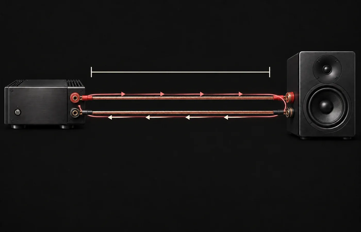
The calculator treats the amplifier as an ideal voltage source and the selected speaker impedance as a fixed resistive load. That simplified model is useful for comparing wire sizes consistently. It doesn’t turn a speaker’s nominal impedance into a constant real-world value.
Worked example: 25 feet, 8 ohms, 16 AWG
A 25-foot one-way run contains 50 feet of conductor. At 4.019 ohms per 1,000 feet, 16 AWG copper contributes 0.20095 ohm. Dividing that by an 8-ohm nominal load gives a 2.5119% resistance ratio, so 16 AWG fits a 3% threshold.
The figures aren’t interchangeable. The 2.5119% resistance ratio is a sizing threshold. The 4.841% figure is the modeled reduction in power delivered to the nominal load relative to the same voltage source with no cable resistance. The level change is expressed separately in decibels.
Copper versus the 10% CCA estimate
The copper-clad-aluminum option is deliberately narrow. It models 10% CCA at 62.9% IACS conductivity, the value listed in the MWS Wire Industries table for 10% copper-clad aluminum. That’s why the calculator multiplies the copper resistance by about 1.5898.
“CCA” isn’t one universal conductor specification. Copper proportion, aluminum alloy, strand geometry and product construction can differ. If a manufacturer publishes resistance for the exact cable, use that value instead of treating this estimate as a product certification.
20°C DC-resistance values for the listed AWG sizes.
Based only on the stated 62.9% IACS conductivity assumption.
Does amplifier power change the recommended gauge?
Not in this resistance-ratio model. Length, conductor resistance and nominal speaker impedance determine the relative voltage and power ratios. Entering 50 W or 500 W changes the estimated watts reaching the speaker and the watts dissipated in the cable, but it doesn’t change which AWG meets a 3% resistance limit.
Power still matters outside this narrow comparison. Terminations, insulation temperature, bundling, installation method and product ratings all affect whether a cable is suitable. The calculator is not an ampacity or electrical-code tool.
Where this model stops
A loudspeaker isn’t a fixed resistor. Its impedance changes with frequency, and a nominal 8-ohm speaker may rise well above or dip below that figure across its operating range. The calculator uses nominal impedance because it’s a practical input for comparing gauges. It can’t predict the exact frequency response of a specific amplifier, crossover, cable and loudspeaker combination.
- Temperature: conductor resistance changes as temperature changes. The published copper resistance table uses a 20°C reference; this calculator does not apply a temperature correction.
- Connections: plugs, binding posts, splices and oxidation can add resistance that is not included here.
- Construction: published cable resistance may differ from a nominal AWG table, particularly for clad conductors and unusual strand designs.
- Reactive behavior: capacitance and inductance are outside this short-run resistance model.
For in-wall, outdoor, plenum or other regulated installations, gauge alone is not enough. Check the jacket and use markings for the intended location. The UL wire and cable guide explains why location and use designations must be checked separately.
Speaker wire is not amplifier power wire
This page sizes the cable between an audio amplifier’s output and a loudspeaker. It doesn’t size the DC cable from a battery or power supply to an amplifier. That separate job depends on supply voltage, current draw, fuse protection, run length and installation conditions. A car-audio power-wire chart can’t be substituted for the speaker-cable calculation here.
Once both speakers are wired, run the left and right speaker test to confirm channel assignment. If bass collapses when both channels play together, recheck polarity at every terminal before blaming cable gauge.